Noise Characteristics of Two-Port Networks
The noise figure definition can be applied for both individual components such as single transistor amplifier, or to a complete system such as receiver.
The overall overall noise figure of the system can be calculated if the individual noise figures and gains of the system components are known.
To find the noise figure of each component in a system, the internal noise added by each stage, N_a, must be found.
The gain must also be known.
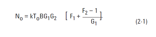
The output noise of two stages system will consist of the $$kT0B$$ source noise amplified by both gains, $$G_1 G_2$$, plus the first amplifier output noise,$$N{a1}$$, amplified by the second gain, $$G2$$, plus the second amplifiers output noise, $$N{a2}$$.
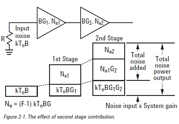
Using equation (1-3) to express the individual amplifier noise contributions, the output noise can be expressed in terms of their noise factors, F.
 With the output noise known, the noise factor of the combination of both amplifiers can be calculated using equation (1-1).
The overall system noise figure of this two stage example will be as the following :
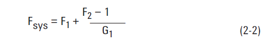
The quantity $$(F_2-1)/G_1$$ is often called the second stage contribution. One can see that as long as the first stage gain is high the second stage contribution will be small. This is why the pre-amplifier gain is an important parameter in receiver design.
This calculation can be extended to a n-stage cascade of devices and expressed as
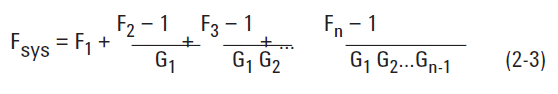
Equation (2-3) is often called the cascade noise equation.
Gain and Mismatch
The device gain is an important parameter in noise calculations.
When the device has a large input mismatch the actual power delivered to the device would be less.
Mismatch loss is the ratio of power delivered, to the power available.
If the gain of the device is defined as the ratio of the actual power delivered to the load to the maximum power available from the source we can ignore the mismatch loss present at the input of the device. It is since it is taken into the account in our gain definition. This definition of gain is called transducer gain $$G_t$$.
When cascading devices, however, mismatch errors arise if the input impedance of the device differs from the load impedance. In this case the total gain of a cascaded series of devices does not equal the product of the gains.
In this case the total gain of a cascaded series of devices does not equal the product of the gains.
Available gain, $$(G_a)$$, is often given as transistor parameter. It is the gain that will result when a given source admittance, $$Y_s$$, derives the device and the output is matched to the load.
Most often insertion gain $$Gi$$ or the forward transmission coefficient $$ (S{21})^2 $$ is the quantity specified or measured for gain in a 50 ohm system.
If the device has a poor output match or the measurement system has significant mismatch errors, an error between the actual system and calculated performance will occur.
If for example the output impedance of the first stage was different from the 50 ohm source impedance that was used when the second stage was characterized for noise figure, the noise generated in the second stage could be altered.
Fortunately, the second stage noise contribution is reduced by the first stage gain so that in many applications errors involving the second stage are minimal.
When the first stage has low gain $$(G^2F_2)$$, second stage errors can become significant.
Noise parameters
Noise figure is a simplified model of the actual noise in a system.
A single, theoretical noise element is present in each stage.
Most actual amplifying devices such as transistors can have multiple noise contributors including thermal, shot, and partition.
The effect of source impedance on these noise generation processes can be very complex relationship.
The noise figure measurement is influenced by the match of the noise source and the match of the measuring instrument.
Designing low noise amplifiers requires trade-offs between the gain of a stage and its corresponding noise figure.
These decisions require knowledge of how the active device's gain and noise figure change as a function of the source impedance of admittance.
The minimum noise figure does not necessarily occur at either the system impedance, $$Z_0$$ or at the conjugate match impedance that maximizes gain.
To fully understand the effect of mismatch in a system, two characterizations of the DUT are needed, one for noise figure and another for gain.
While S-parameter correction can be used to calculate the available gain in a perfectly matched system, it can not be used to find the optimum noise figure.
A noise parameter characterization uses a special tuner to present different complex impedance to the DUT.
The dependence of noise factor on source impedance presented by the tuner is described by